Whole-core CT, micro-CT and nano-CT provide imaging options across scales. Investigate internal structure and sample condition, then connect selected volumes with digital-rock analysis and upscaling.
3D VOLUME / CUTAWAY
Real CT imagery · interactive view loading.
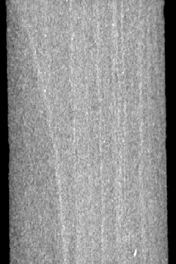
Real plug CT · ≈103 µm source sampling Colour reveals attenuation contrast, not calibrated density.
THE QUESTION
Is the sample representative and suitable for the test?
CT provides a view inside the rock before destructive preparation or testing. Image review can reveal features that influence sample selection and help interpret laboratory behaviour. Follow-up imaging supports sample-condition checks during an agreed analytical sequence.
Methods & applications
Whole-core, plug and sidewall-core CT imaging
Micro-CT and nano-CT acquisition
Fracture, bedding and structural observations
Sample screening before advanced studies
Repeat imaging to monitor sample integrity
Circumferential imagery for core–BHI integration
FROM ACQUISITION TO UPSCALING
Start with the scan. Connect the scales.
Geotek XCT acquisition
Capture internal core structure in a three-dimensional CT volume that can be revisited for further review. Whole-core observations can guide complementary CoreDNA logging and targeted sampling. Scan settings are selected for the sample dimensions, condition and imaging objective.
Micro-CT
Investigate selected plugs and smaller specimens at a finer scale, connecting internal texture and resolved pore structure with the whole-core context. Sample dimensions, field of view and the required image detail guide the acquisition plan.
Nano-CT
Extend the investigation to finer features in suitably prepared small specimens or selected regions. The achievable resolution, sample preparation and representativeness are assessed for each study; a highly detailed local view must still be related to the wider rock fabric.
CT upscaling
Connect detailed digital-rock analysis with the larger-scale core context. Depending on the available images and reference measurements, a scoped programme can combine segmentation, multiscale characterisation and property upscaling within a workflow.
AI upscaling
Explore AI-assisted image enhancement and super-resolution as a specialist extension to the CT workflow. Suitability is assessed against the input images and the intended interpretation, with validation requirements defined before the work begins.
Keep measurement and prediction distinct AI-enhanced images are model-derived outputs, not newly acquired high-resolution scans. Image enhancement and physical-property upscaling answer different questions. Outputs retain their provenance, assumptions and validation status.
Denoising and super-resolution can be scoped alongside CT acquisition to support clearer image interpretation. The approach is selected for the scan, the rock and the question—not simply a larger pixel count.
01→
Acquire
Original CT volume
Retain the source scan, sampling information and acquisition context.
02→
Enhance
Denoising & super-resolution
Assess AI-assisted noise reduction and super-resolution against the imaging objective.
03→
Check
Compare with reference evidence
Review preserved structures, uncertain features and suitability for downstream analysis.
04→
Connect
Segmentation & digital rock
Pass suitable image products into a documented interpretation workflow.
Image enhancement is not a new acquisition.
Super-resolution produces model-derived image detail; it does not change the original scan’s acquired resolution. Original and processed volumes remain distinguishable, with validation requirements agreed before quantitative use.
CTS can scope specialist image enhancement, segmentation, super-resolution and flow simulation around your dataset. Technology selection, suitability and validation requirements are defined for each programme.
Cross-calibrate CT attenuation against independent gamma-density measurements to investigate higher-resolution density variations. Review mineralogical changes, core ends and the selected image region before extending a calibration.
Mercury-free bulk volume
Use a scoped CT-based bulk-volume workflow for suitable core plugs. Define the external boundary, resolution and validation approach before combining the volume with independent grain-volume measurements for porosity.
Sample integrity through testing
Compare scans before preparation, after cleaning and after laboratory analysis. Track fractures and changes in sleeved or mounted plugs to help interpret the test sequence.
Orientation and targeted sampling
Use internal bedding and fracture geometry to guide slabbing and plugging. Relate circumferential CT imagery to borehole images where suitable matching features support orientation.
CT attenuation is not a direct measurement of mineralogy or strength. Density conversion requires an appropriate calibration; scan resolution and sample suitability are agreed for each programme.
CTS is your point of contact for planning the programme and bringing the results together. Where specialist laboratory or interpretation input is required, delivery responsibilities are identified in your proposal.
The scope distinguishes the measurement package and its included outputs from additional processing, interpretation and interactive reporting. Sample requirements and method limitations are confirmed before work begins.
A CONNECTED WORKFLOW
From question to evidence.
01
Define the feature and scale of interest
02
Acquire and check the scan
03
Review structure and sample condition
04
Connect observations to interpretation
Interpretation boundary A low-attenuation feature is not automatically a resolved pore network. Quantitative pore-scale interpretation requires suitable resolution and independent checks.